Field Assignment:
1/ Take a scan of something with a significant Delta-T within the scan.
Freeze the scan (don't save it if you want to do this on the camera vs. your computer).
2/ Put a "spot" measurement tool on the warmest and coolest spots in the scan.
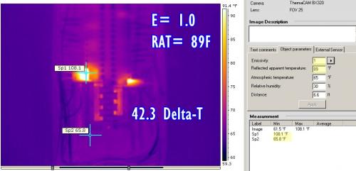
3/ Set the camera emissivity to 1.0 and Set T-Reflect to 89
4/ Record both spot temps and subtract and determine the delta-t between them.
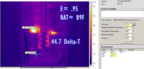
5/ Change the emissivity setting to .95 and then .50. Record the temps and delta-t's again for each.
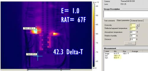
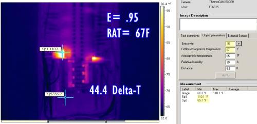
6/ Now set the emissivity back to 1.0 and change the T-reflect from 89 to 67.
7/ Record the same measurements at emissivity 1.0. .95, .50 as you did above.
Compare the results:
1/ What difference occurred with the spot measurements when emissivity was changed? (> 40 degree change?)
2/ What difference occurred with the differential measurements when emissivity was changed? (> 10 degree change?)
3/ What difference occurred with the spot measurements when the Temp Reflect was changed?
The temperature in the room (or in the scan) never changed but what did change and by how much?
We determine how hot is too hot in electrical panels by the delta-t practice. It can be between the component and the panel ambient or component to component (under the same load like 2/3 fuses on the same circuit).
How does the above exercise effect your call to repair now, later or never?

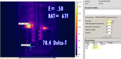
A couple of things we should notice:
1/ ignoring the temperature reflect setting of 89° on the camera and adjusting for emissivity only; produces an "apparent" 17.7° dT between emissivity settings from 1.0 to .5.
Ignoring the temperature reflect setting of 67° on the camera and adjusting for emissivity only; produces an "apparent" 34.8° dT between emissivity settings from e1.0 to e.5.
This produces an error factor of 17.1° in your "apparent temperature" readings displayed by the camera.
This situation can occur if you neglect to adjust the camera when you move from outdoor scanning to indoor scanning and fail to change the temperature reflect.
2/ however even more significantly, the differential between improper emissivity settings between e1.0 and e.50 is 44.3° with a temperature reflect setting of 89°; and 36.1° with a temperature reflect setting of 67°. This creates an error factor of 8.6°.
In the example we are demonstrating here, where a circuit breaker reading is an "indirect" measurement. These temperature differentials are only a percentage of the actual internal temperatures of the components (see Direct versus Indirect measurements). An "indirect" temperature differential of a mere 8.6° may become "significant" and require immediate action when considering what a "direct" temperature measurement would produce (most often is not ever accessible).
In this example our lowest emissivity was only e.50. In electrical panels, there are many objects that have much lower emissivity where bare conductors, terminal blocks and buss bars are concerned.
It is always recommended that low emissivity objects (below .50) be avoided as they are highly susceptible to the surrounding ambient conditions specifically those that affect the "Temperature Reflect".
Pay attention to where you place your spot measurement tool or where automatic temperature measurement tools focus. These temperatures may, or may not indicate proper temperature readings.
There are circumstances where low emissivity objects become accurate measurement locations due to their "geometry". We will discuss this at another time.
Keep in mind when you place spot temperature tools on your scans that you cannot compare temperatures between two objects in the scan that are not of the same emissivity. I see this situation very frequently. In this exercise, we saw an error factor as much as 35°!
A significant temperature differential in an electrical panel is 40° Fahrenheit.
Not much room for this kind of error factor!


Comments
Post new comment